top of page

Rebuild Progress
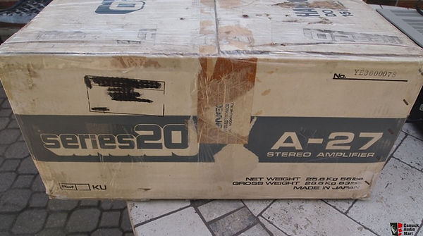
Photo from the original website listing.
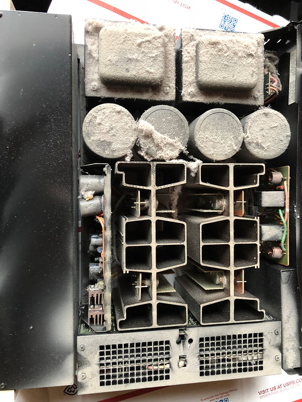
Years of dust build up.

Years of dust build up.
Bottom view after blowing out.
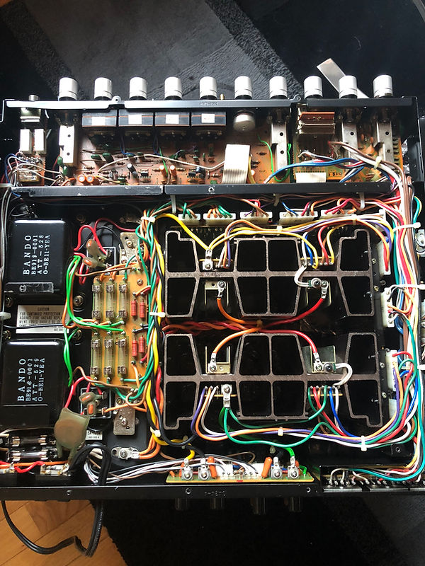
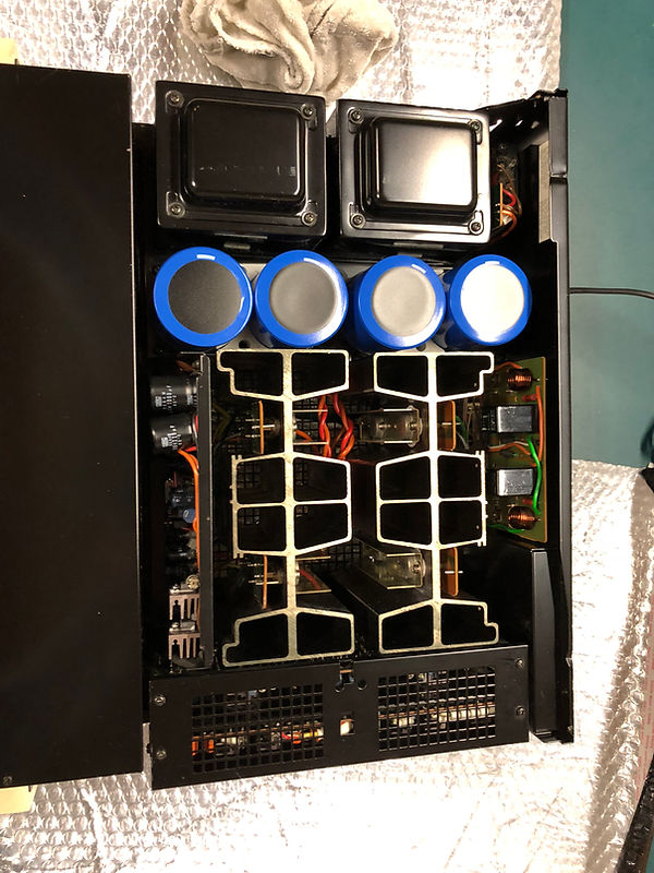
Top view after blowing out. Extremely clean with no rust or loss of paint and minimal heat damage to the boards.

First step was replacing the large and expensive forty year old 18000uf 70vdc power filter caps in order to bias later with greater reliability (early testing showed that the Power Supply board would not bias correctly, well under expected voltage while producing a low level audible hum at the speakers). Each filter cap was was marked for later ID and new cap orientation.

Large filter caps are connected beneath the fuse board.

No leakage discovered from any of the four filter caps.
New 22000uf 80vdc caps were mounted and connected with direct fit - only a minor modification required to one terminal hole placement on two terminal straps. Extra rubber spacers and longer screws were added to better isolate fuse board.

Next step was replacing the thermal transistor paste and new mica insulators to better protect the unobtanium transistors from excess heat. Each of the heatsink assemblies were easily disconnected and removed one at time.
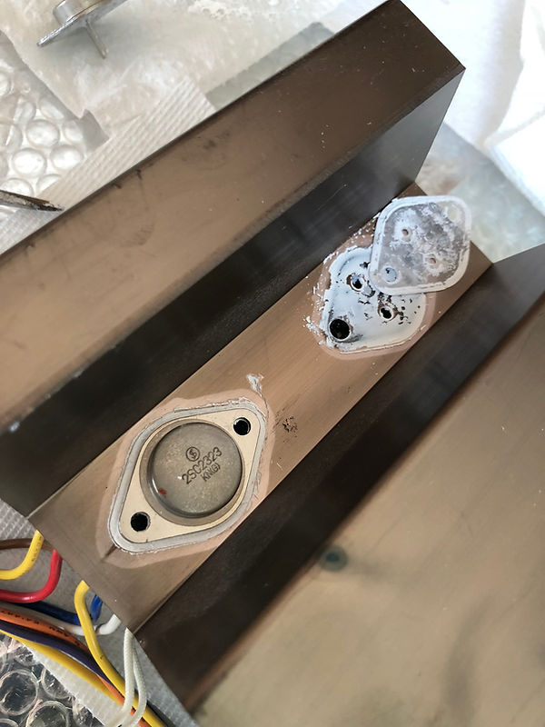
Carefully removing the two screws and lifting up on the transistors dislodged them their mounts. I marked each for reassembly placement. Forty years and heat completely dried up the compound on all of these, easily removed with alcohol.

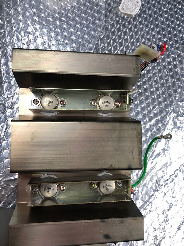

New thermal compound was applied to both sides of new mica, transistors were reset into their original positions and mounts.

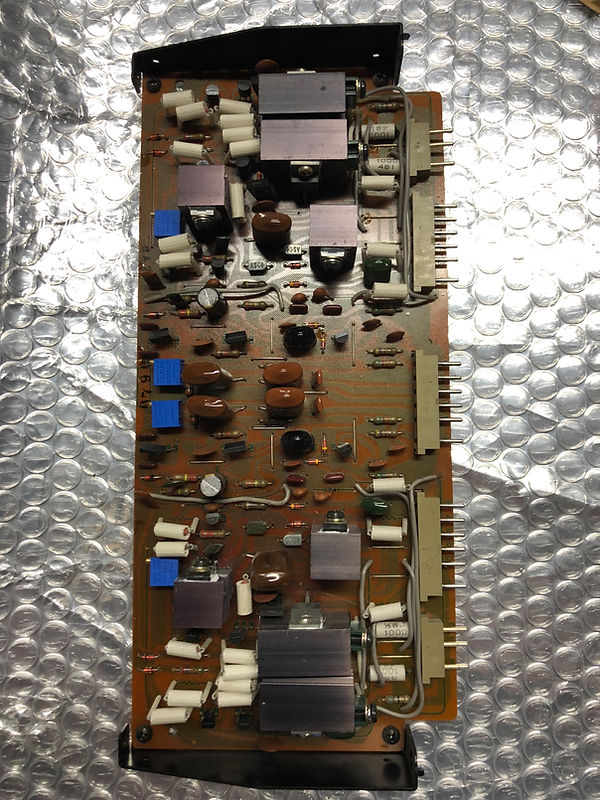
Next step was to recapping, repotting, and cleaning terminals on the Power Supply board. These are the before pictures...


Power Supply board before...
Power Supply board before...
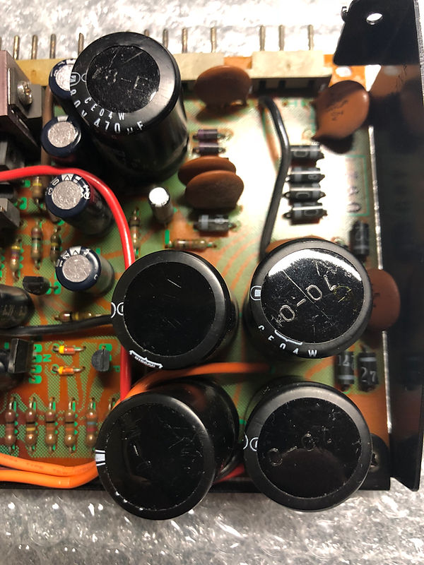
Power Supply Board before...

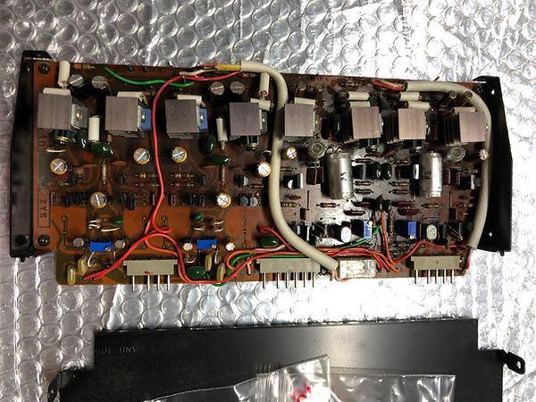
Power Supply Board after recapping and repotting (side facing pot adjustments face up after board was mounted for easy biasing.

Terminals were cleaned and polished using a pink school eraser.


New 28 turn pots allowed for easy and and accurate biasing of the circuit. Spec'd voltages were right on.

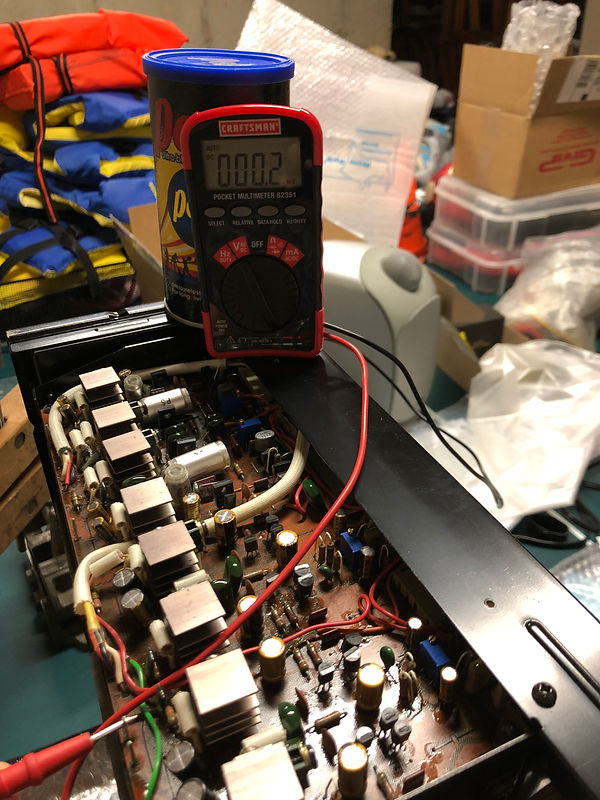
Testing audio after rebuilding each board made it easier to isolate any work issues (though none found). After Power Supply board was rebuilt and rebiased, all audible hum vanished from the speaker outputs. Zero noise was audible after this stage of the rebuild. Power transistor heat sinks ran much hotter now.

Amplifier and Phono Boards were easily removed with several connectors for this next step.

Amplifier Board shoing four new pots installed and several caps replaced. Terminals were also polished.
Phono Board with four new pots and several caps replaced. Terminals were polished.

Both boards were easily set in place, ready for rebiasing...


Power Amplifier LEFT and RIGHT Idle Current set at 88mv.


Power Amplifier LEFT and RIGHT DC Balance set for 0v.


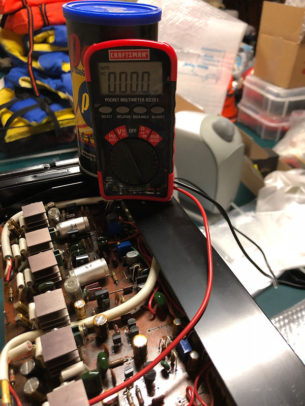
Phono Board MC and Equalizer LEFT and RIGHT bias set at 0V

Tone Board required full removal of faceplate and careful removal of the boards to recap while still wired in.

Volume and Selector boards also where removed from the faceplate to recap while still wired in.

And finally, the 40 year old speaker relays are no longer available. I removed both by first removing the rear channel heat sink assembly, than the speaker terminal board to desolder and remove the relays. After removing, I disassembled both relays to clean both sides of contact points by running thin Deoxit soaked cardstock between the closed terminals - now shinny and new.

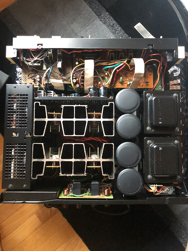
Final assembly and break in. When correctly biased, the heatsinks get very warm to touch and after 30 minutes this amp generates plenty of heat for the room (I believe Pioneer may have miss printed "...first 3 watts Class A." Possibly someone with the right test equipment should be able to test if it should read "first 30 watts in Class A!"
bottom of page